IronRidge Racking - Ground Mount
OVERVIEW

IronRidge Ground Mount combines the strength of XR1000 rails with locally-sourced steel pipes to create a cost-effective structure capable of handling any site of terrain challenge.
Installation is simple with only a few structural components and no drilling, welding, or heavy machinery required. The System works with a variety of foundation options, including concrete piers and driven piles, and can support up to 5 modules per column.
Features
 |
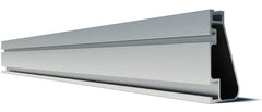
XR1000 RailThe strongest rail in the industry makes it simple and secure to assemble columns of three to five modules. |
 |
Caps & ConnectorsTop Caps and Rail Connectors are the only components needed to attach XR Rails to cross-pipes and vertical piers. |
 |
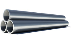
Schedule 40 Pipe (Item Sold Seperately)Locally-sourced 2" or 3" schedule 40 pipe allows you to save on freight, while still spanning as high as 18' between vertical piers. |

IronRidge Standard Rails Assembly
Modules are clamped to XR1000 rails to create a column between the North (high) and South (low) cross pipes. The unique spanning capabilities of XR1000 rail support up to 5 modules per column in landscape orientation.
All components for the rail assembly are available in clear or black finishes, and clamps are available in a range of sizes to match all common module frames.
 Top Cap & Rail Connectors
Cast aluminum Top Caps quickly attach to vertical posts with set screws, and also support cross pipes using companion U-bolt hardware. Top Caps are available for 2” and 3” schedule-40 pipe. Rails Connectors attach XRS Rails to the cross pipes using 3/8” nuts and bolts.
 Schedule 40 Galvanized Pipe
The Ground Mount System uses schedule--40 steel pipe as the primary structural element.
Locally-sourced steel pipe minimizes materials and shipping costs, while increasing the speed and flexibility of construction.
In addition, the Ground Mount System works with concrete piers, pile-driven piers, and many other foundation types.
TECH SPECS

| Module Tilt Range: | 0 to 45 degrees |
| E-W Pier Spacing: | Up to 17' |
| N-S Pier Spacing: | 7' 6" |
| Max Wind Speed: | 150 Mph |
| Module Orientation: | Landscape/Portrait |
| Wind Exposure: | Category B, C & D |
| Maximum Snow Load: | 60 psf |
| Materials: | Aluminum |
| Cast Steel ASTM A216 | |
| A53 GR B (SCHED 40) | |
| Stainless Steel Fasteners | |
| Warranty: | 20 Yr Mfg, 10 Yr Structural |
| Locally Sourced Pipe: | Yes. Must be Schedule 40. See Engineering Guide for details. |
| Additional Bracing: | Yes |
| Adjusts to Elevation Change: | Yes |
| T-Bolts: | Yes |
| Wire Clips: | Yes |
| End Caps: | Yes |
| All Metal Construction: | Yes |
| Engineering Support: | Yes (P.E. Certified) |
FREQUENTLY ASKED QUESTIONS
-
When should I use 3” versus 2” Schedule 40 steel pipe for my sub-structural material?
2” Schedule 40 steel pipe is generally used for smaller arrays, such as residential applications, because it’s lightweight and easy to handle. 3” Schedule 40 steel pipe is most useful for larger arrays, where the longer E-W span helps reduce the number of concrete foundations. But, 3” Schedule 40 steel pipe is also heavier and sometimes requires heavy machinery for installation. Before purchasing your pipes, confirm the specifications with the Ground Mount Engineering Design Guide.
-
Is UL 2703 a new standard?
Locally-sourced 2" or 3" schedule 40 pipe allows you to save on freight, while still spanning as high as 18' between vertical piers.
-
How should I splice my Schedule 40 steel cross pipe?
Threaded couplers are the most common method for splicing Schedule 40 steel pipe. This requires that you order “threaded pipe” from the manufacturer or that a threading tool be available onsite. Welding the pipes directly to one another or using welded couplers are also acceptable options. Keep in mind that splices should not fall within the middle third of the span or on the end span (cantilever) of the cross pipe.
-
My soil is very rocky. Do you have any foundation designs aside from concrete footings?
IronRidge provides standard foundation sizes for various soil classes. However, some soils may be extremely difficult to dig into, such as granite or rocky soils. Solutions for these soil types include epoxying rebar into the granite and pouring the foundations above the ground, connecting the piers with low depth grade beams, or casting the piers into above ground ballast blocks. Consult an engineer for structural review if using a foundation design other than those described in the IronRidge Certification Letters.
-
What determines my North to South pier spacing?
North to South pier dimensions are static measurements in our Ground Mount design that are either 7.5’ or 9’, depending on the number of modules per column. Refer to the assembly drawing found at the bottom of the IronRidge Certification Letter for dimension details. The certification letters can be found in the System Support section under the Ground Mount tab on the IronRidge website.
-
What design constraints should I be aware of when building an array on an East to West slope?
The maximum “above ground length” for the southern vertical piers is 2’6”. To prevent exceeding this length on either side of the array, break the array into segments. This “stepped” array will prevent the East or West side of the array from being too high. If this is not a viable option, consult an engineer for alternative approaches.
-
How do I suspend my vertical piers while I pour concrete?
Many installers create a temporary set of “forms” to suspend the East to West cross pipes, with the vertical pipes already attached to them. This approach allows you to assemble and level your sub-structure at the appropriate height, then pour all of the concrete at once. Always refer to the Ground Mount Installation Manual prior to assembly.
-
How do I calculate row spacing to avoid shading?
This question depends on what is considered an acceptable amount of annual “shade loss” (system output lost to inter-row shading). If your goal is zero shade loss, visit the first the NOAA Solar Calculator (http://www.esrl.noaa.gov/gmd/grad/solcalc/) to find the minimum solar altitude angle (El) on December 21st at 10 A.M., by inputting the coordinates of the project area. Use the following formula to find distance (D) between arrays to avoid shading: D’=h/tan(El). Height (h), is the difference between the rear edge of the first array and leading edge of the second array.
TRAINING & HELP
Installation
GoGreenSolar.com is a direct distributor of IronRidge parts and components. View our complete line of DIY solar kits that include IronRidge racking.
We're experienced solar veterans, providing custom solar solutions since 2006. Our work has been featured on CBS, Price is Right, and USA Today. Choose us for a boutique, complete service experience - we help you every step of the way until you're generating free energy from the sun.

Solar Calculator

Which Solar Kit Do I Need?
GET STARTED WITH SOLAR
WE’LL HELP YOU FIGURE OUT YOUR SOLAR NEEDS!
Fill out the form for a complimentary solar quote that includes a custom satellite layout, system design and a breakdown of total project cost and estimated savings.

 Top Cap & Rail Connectors
 Schedule 40 Galvanized Pipe